Base + pad
The rounded red plastic base holds the white slotted tube and is supplied with a polystyrene pad. Ground conditions and stability requirements must be confirmed.
A reusable support system that holds the stringline through an above-ground base, upright and adjustable connection.
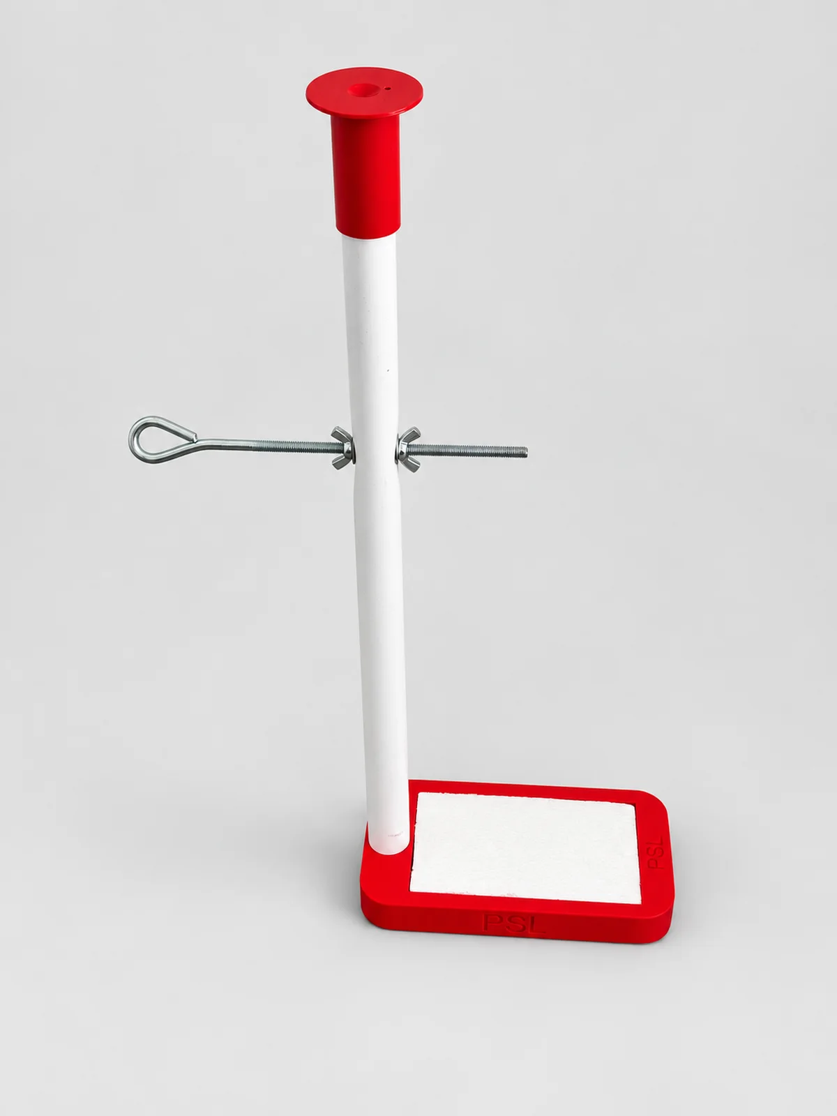
The starter box includes chrome end caps for the backs of the bolts; these are not fitted in every development photograph.
See the assembly in the supplied product photographs.
The rounded red plastic base holds the white slotted tube and is supplied with a polystyrene pad. Ground conditions and stability requirements must be confirmed.
The white slotted tube carries the stringline connection. A red plastic safety cap fits at the top. Dimensions and material grade are to be confirmed.
The pigtail bolt provides the stringline connection through the tube slot. The starter box includes a chrome end cap for the back of each bolt. Adjustment limits are to be confirmed.
The starter box includes 100 m of red stringline and 10 support assemblies. Actual support spacing and tension must follow the confirmed instructions.
The proposed installation sequence below follows PSL’s brochure draft. It describes the workflow; fixing, ballast, spacing and tension limits still require technical confirmation before this becomes an issued installation guide.
Driven setting-out pins are not required. Optional nails are still ground penetration: establish service locations, surface restrictions and the approved working method first. Do not use nails where shallow services or bridge-deck waterproofing may be affected.
Mark the required support positions on the ground using a one-pence coin, as described in the PSL brochure draft. Keep the total station set up.
Place the socket so the stringline-holding part of the pigtail bolt sits vertically above the mark.
Use the site-approved fixing and ballast arrangement. The draft proposes nails through the polystyrene mattress only where ground penetration is permitted, together with a sandbag or similar ballast. Nail length, quantity and required ballast must be confirmed for the installation.
Use a mini prism or equivalent survey method to measure to the line position, then adjust the pigtail bolt for line and level.
Position and fine-tune each socket to the required setting-out control.
Set an anchor at or just beyond the start of the kerb run using the same PSL base fitted with an unslotted tube. Where appropriate, the starter-box kerb clamp provides an alternative connection to an existing kerb.
Position an anchor just beyond the end of the run using the same PSL base fitted with an unslotted tube. The anchor arrangement takes the full stringline tension. Restraint and ballast must suit the intended tension; use an approved mechanical lifting method for heavy ballast.
Attach the line to the first anchor and pass it through the pigtail eyes at the intermediate stations. These slotted-tube supports hold and adjust the stringline to correct sag, line and level; the anchors take the full stringline tension.
Secure the line at the end anchor and apply only the tension appropriate to the verified anchor and support arrangement. Do not rely on an unverified ballast quantity.
Check alignment, levels and dips along the run before handing over to the kerb-laying gang.
After the kerbs and backing are complete, retrieve the PSL components, inspect their condition and prepare them for the next set-out.
Use a suitable non-penetrating, ballasted arrangement. Do not use nails. Buried-service procedures remain necessary.
Use a suitable non-penetrating arrangement that protects waterproofing. Obtain confirmation of deck and ballast suitability.
A ballasted arrangement can avoid penetration. The draft also proposes masonry fixings where specifically permitted; nail size, embedment and the need for ballast require site-specific confirmation.
Anchors use the same PSL base fitted with an unslotted tube and take the full stringline tension. Intermediate stations use slotted tubes and pigtail bolts to support the line, correct sag and adjust line and level. Rated tension, ballast and span limits remain to be confirmed.
The issued brochure will include confirmed fixing details and operating limits. Request installation information.
PSL eliminates the need for traditional driven setting-out pins. Choose a suitable ballasted arrangement to avoid ground penetration; optional nailed installations still penetrate the surface and require appropriate site controls.
Adjust the pigtail bolt for line and level to target millimetre accuracy and help reduce rework. Achievable accuracy depends on survey control, setup, line span and tension; verified performance figures are not yet available.
Designed for fast installation, adjustment, removal and relocation as work progresses.
Reusable components reduce dependence on disposable or replacement setting-out equipment. Service life depends on use, inspection and care.
Leave driven setting-out pins behind. Put Perfect String Line to work on your next kerb line.